Electrical system health
How many of you start an electrical diagnosis by checking the battery state
of charge or charging system voltage? I’m not saying you don’t, however, in my travels, I
have been to many different shops and have seen this overlooked a lot.
Good source voltage is extremely important, more so in modern vehicles.
Solenoids, actuators, sensors, switches, and computer modules are needed to operate a modern
automatic transmission, which is a substantial demand on the electrical system. If
the source voltage is low or unstable those components will not operate correctly and cause
any number of driveability complaints or possibly lead to unit failure. Any diagnostic
results taken with poor supply voltage could lead to misdiagnosis. We must verify the
integrity of the system before proceeding. Of course, Moveras’ focus is automatic
transmissions, but electrical principles apply just the same in the entire vehicle.
Battery state of charge
Safety is most important:
YOU MUST KNOW WHAT YOU ARE WORKING ON AND HOW IT WORKS. If you’re
working on an EV or Hybrid vehicle with High voltage systems there are
several safety measures that must be taken before touching the electrical system, refer
to the factory service procedure on making the high voltage system safe prior to any
work.
*Note, If you’re
working on a vehicle with an auxiliary battery or duel battery
system you need to isolate the batteries from each other during this test
or one may mask an issue with the other.
Start by measuring the battery voltage at the battery terminals with a
high impedance (10 megaohm) digital volt-ohm multimeter
(DVOM). A standard 12-volt lead-acid battery is made up of 6 cells that, in good
condition, measure 2.1 volts each, so with that, your reading should be 12.6 volts. There
are other factors like surface charge and system draw that could affect this reading up or
down. Surface charge may be present if the vehicle was recently running, and the battery was
being charged. If that is the case turn on a few loads such as the headlights and windshield
wipers for a couple of minutes, then shut off the items you turned on and the voltage should
stabilize close to 12.6 volts.
If you have low voltage and notice it dropping consistently you may have a
draw on the system, however, vehicles today have a lot of computers in them, and they draw
on the battery when they are “awake”. In order to test for a draw you will need to find the
manufacturer's procedure to put them all in “sleep mode” before testing for a draw. If you
notice a draw you will want to consult the factory service manual and look up what the
acceptable amount of draw is. Any draw will eventually drain the battery, so it is good to
use a battery maintainer/charger for long-term vehicle storage.
Battery load test
This should be performed next. If you have a battery load tester that is
the correct way to assess the battery, any other tests are
subjective. A process that has worked for me in the past, is to turn on every
electrical load you can find, like, the HVAC fan on high, rear window defrost, wipers on
high, headlights on high beam, fog lights, hazard lights, interior lights, etc. with your
meter connected, and the vehicle ignition in the run position while the engine is
off. If the voltage drops below 10.5v during this test the battery
should be replaced.
*If the vehicle has an electric cooling fan you can
turn it on with the bi-directional control
feature in the scan tool.
The fan will easily draw over 20 or 30 amps. If
bi-directional control is not available simply jump the fan relay.
Another way to load the battery is to use the vehicle's starter. Start by
disabling your fuel or spark to prevent the vehicle from starting. With your meter connected
to the battery terminals and visible from inside the vehicle, crank the vehicle for no more
than 15 seconds. Because this test will put more load on the battery than the test above,
you should not see the voltage drop below 10 volts during cranking.
In either of these tests, the recovery time should be fairly quick, and the
battery should return to around 12.6 volts.
Charging voltage
With the multimeter still connected, reverse what was done to disable the
vehicle from starting and start the engine. With the engine running at idle, you should see
13.5 to 14.5 volts at the battery terminals. You must load test the alternator too. You want
to turn on as many loads as possible and see if your charging voltage remains at 13.5-14.5,
if so, your system is working correctly.
*Important- the specifications listed here are general and not specific
to any make, model, engine size, battery type, or charging system. It is in your best
interest to look up your specific application, again know
what you’re working on and how it works.
Voltage drop testing
A tried and true method of testing electrical circuits is voltage drop, and
it is the preferred method for several auto manufacturers. Unlike resistance testing which
must be done only when power is removed from the circuit, Voltage drop tests must be
conducted on a live circuit under load. This is a major advantage because resistance testing
will not prove the circuit is capable of carrying current (amperage), however voltage drop
will. Once you have perfected your method of voltage drop testing it will become your
preferred method too.
What is voltage drop testing? It is a measurement of the voltage consumed
by the resistance between any two points you’re measuring. If you remember back to basic
electrical class, you need voltage to move amperage through a resistance. This form of
testing shows where the voltage is being consumed in a circuit. In an ideal world, voltage
would only be consumed by the load in the circuit, meaning that all the energy went to the
component the circuit is powering. We don’t live in an ideal world and superconductors are
not used in automotive, so we have resistance points other than the load in the circuit.
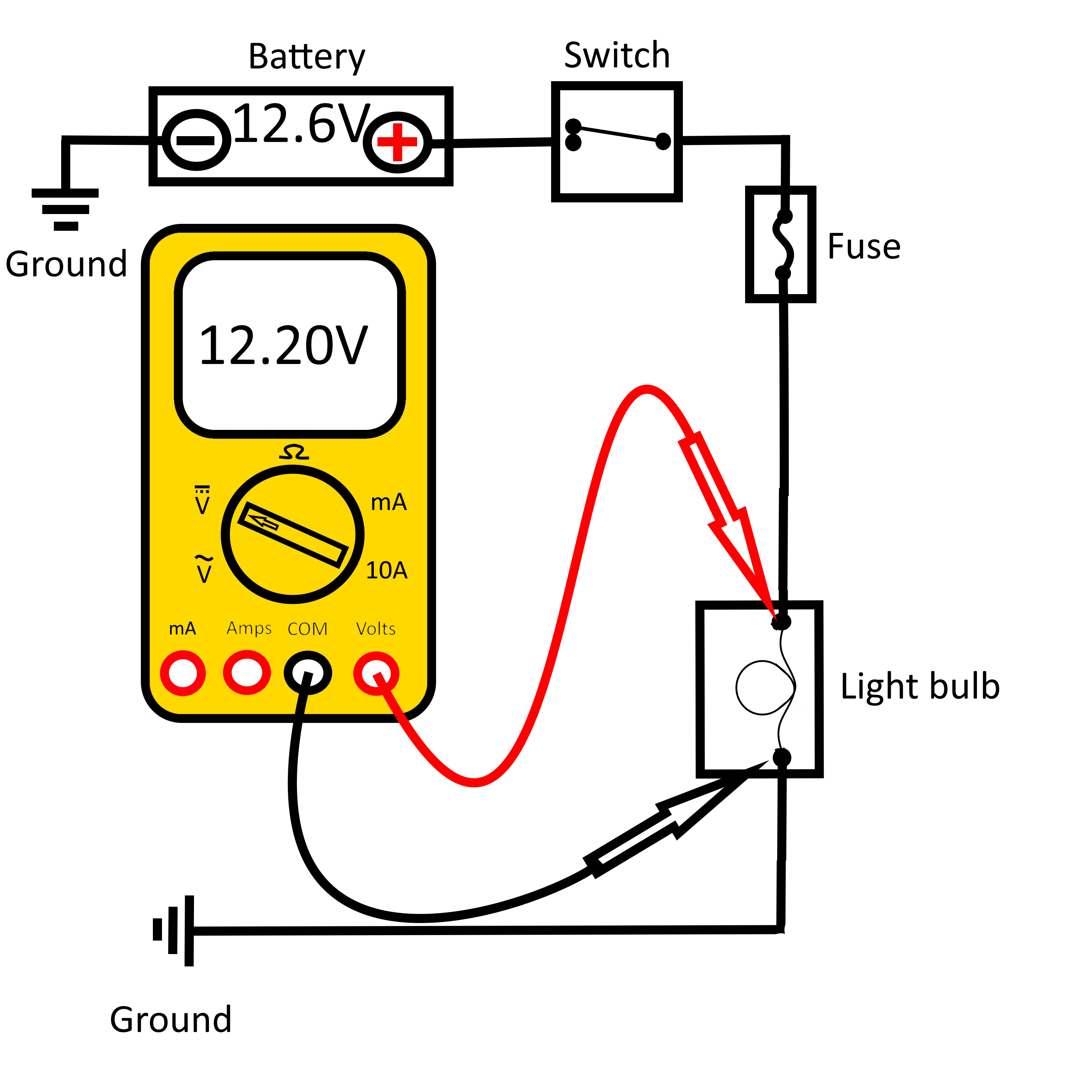
As a general rule, there is an allowance of .1 volt per connection in a
circuit, this drop is due to the resistance of each connection. In Fig. 1 the battery is at
12.6 volts, because there are 9 connections, and each is allowed .1V per connection you may
have a drop of up to .9 volts (900mv) across the entire circuit. The DVOM is reading 12.2
which means the light bulb consumed 12.2 volts of the available 12.6 which means the circuit
only consumed???? Yes, .4 volts (400mv), which is less than the allowance.

Fig. 1
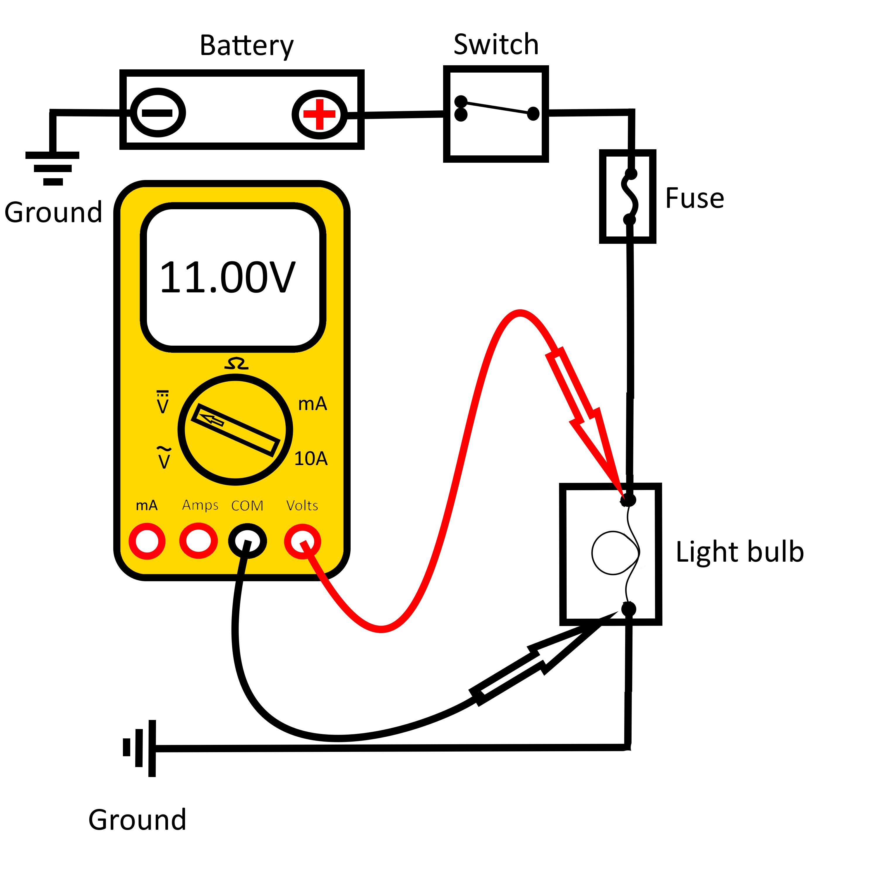
In Fig.2 the circuit consumed more than 1 volt because the light bulb only
was able to consume 11.0 volts, which means we need to find the other 1.6 volts. Further
testing would be needed until you find the point that is consuming more than allowed.

Fig. 2
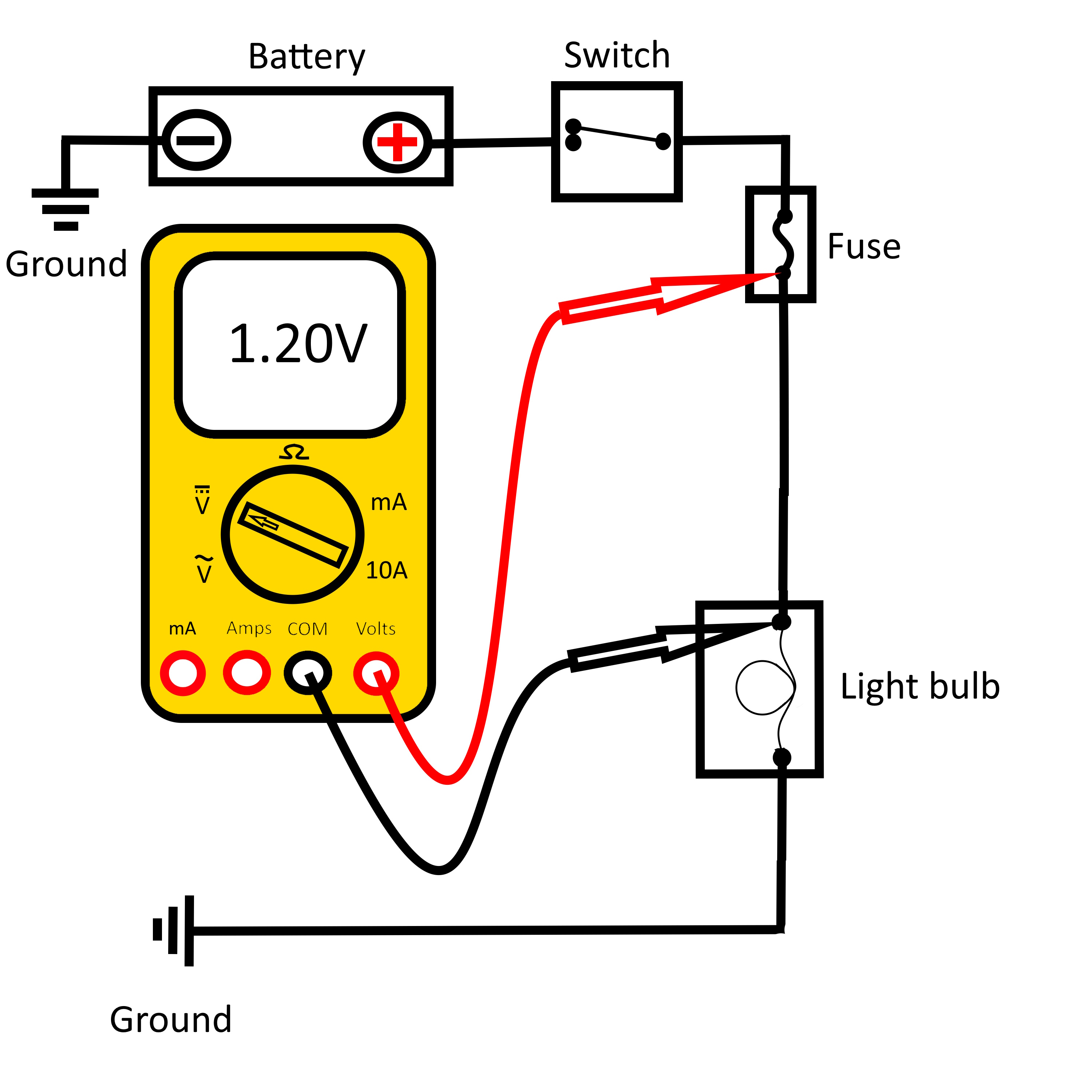
When we tested between the fuse and the light bulb, we found a 1.2 volt
drop as seen in Fig.3.

Fig. 3
In this case, a good visual inspection of the wiring between these two
points should be done. You may find damage to the wire, corrosion, loose connections etc.
Don’t forget to check your grounds!!! The same rules apply to the negative
side of the circuit as the positive. Check the battery negative to the engine block and the
body to ensure you are not consuming voltage on the ground side of the circuit. It helps to
look at an electrical circuit as a loop and any part of the loop affects the entire circuit.
*Something that may be overlooked is pin tension. Male and Female
connections must be tight to make good contact! There are tools that will measure
pin tension, or you may make your
own. If you will be doing
this type of diagnostic work, it is
strongly recommended to have something to check this.
Case study
Voltage drop testing can be used on any Direct Current system, while
diagnosing a failed starter on a tractor, it was determined that the battery terminals were
faulty.
As you can see on the left, the cable going into the terminal looked good,
nothing indicated what we found inside. When we peeled back the wire covering it was evident
that we found a problem. There was a voltage drop of 4.5 volts between the terminal and the
connection point at the starter. This showed us where to look for the problem.
*There is another method of testing that has
become very fast and helpful, and that is thermal
imaging. With a thermal imager, you will see the heat that is a byproduct of high
resistance.
How does bad battery terminals lead to a faulty starter you ask? Remember a
healthy battery has 12.6 volts of potential. If 4.5 volts are consumed before it reaches the
starter, then only 8.1 volts are getting to the starter. The amperage at this point must go
up in the circuit to overcome the resistance (Ohms law), this causes components to overheat
and fail, which is exactly what happened to the starter. This example will apply to all
electrical components in the vehicle, so, you can see how important it is to have good
connections, especially at the battery terminals.
Summary
Keeping with our theme of back to basics we need to remember to check the
easy stuff that can cause us the biggest headaches. It doesn’t get much easier than checking
the source voltage and battery terminal connections. With the testing processes outlined
here, we hope that this will speed up the process with the most accurate results.